The Solid Tools file is a supplement to the Perspective Tools. To use these tools effectively, it will be necessary to download both files.
![]() Perspective_Tools June 6, 2010
Perspective_Tools June 6, 2010
![]() Solid_Tools June 6, 2010
Solid_Tools June 6, 2010
Some traced solids were developed shortly after the perspective environment was created. Several years later, I got a useful suggestion from Dr. Krongthong Khairiree, an educator and Sketchpad authority from Thailand. She told me to use the Perspective Tools with iterated constructions. This led to several useful constructions, which I then converted to tools. Then later still, I had an extended exchange with Mario Duarte, of Houston. This led to the simple group of tools, which are not as versatile, but are much more accessible. With the release of GSP5 in 2009, the new display was incompatible with many of the old tools, so they had to be rewritten. In the process, I found a method for creating hollow surfaces with a contrasting interior color. The Solid Tools file carries all of the tools listed below. I recommend learning them in the order they appear here.
Some significant changes have been made to these tools to make them compatible with GSP-5. For an explanation of these changes, see GSP-5 Issues.
All of the solids described here require a perspective environment, and the setup tools for that environment are found in the Perspective Tools file. First execute Perspective Setup.
For all tools outside of the simple group, Sundial and Colorbar are also required. The sundial controls the direction of the light source. The colorbar controls the color of the solid.
For the hollow surfaces, Interior Colorbar is required. This controls the color of the interior surface.
The Freeze Sun tool is not required in any case, but it is a useful option that applies to all of the parametrically colored surfaces. It causes the light source to stay fixed as the coordinate system and plotted objects are turned. These controls are explained in more detail on the Perspective Controls page.

As with the other objects, the points that define the solids are referenced to the x-y center and the z center. After an iterated or traced solid is constructed, a crude projection will appear in the x-y plane. This is to help with the alignment of the objects.
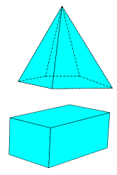
The tools in this first group are the simplest and probably the most useful. In fact, they can even work with vertices that have been plotted by someone else’s perspective tools. Construct the vertices first. Choose a tool from the list of polygon names, 3‑gon through 6‑gon. Select the vertices in counterclockwise order. This will construct the sides of the polygon and cyan interior. When the face is turned away from the viewer, these objects will vanish.
There is a second group of tools with the front/back label. These are implemented in the same way, but when the face is turned away, the interior vanishes and the edges are replaced by dashed line segments. This gives the solid a transparent effect. In the image shown here, the pyramid was constructed with 3‑gon front/back and 5‑gon front/back; the cuboid was done with 4‑gon.
For a face with more than six edges, choose Define Plane (simple). In counterclockwise order, select any three points in the plane of the face being drawn. This creates some hidden calculations to be used by the tools that follow. Draw the edges using either Edge or Edge front/back. Be sure to get all of the edges, including those that are already showing on adjacent faces. Construct the polygon interior using the regular Sketchpad tool. Choose Face (simple) and click on the interior. This creates a cyan-colored image of the original face right on top of it. After that, it is necessary to hide the pre-image. The new interior will vanish when the face is turned away.
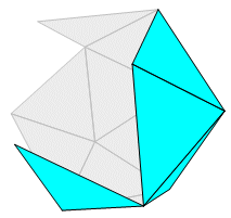 Yet another face tool was made possible by some of the new features in GSP-5. Use 2-Face (simple) in the same way described above. What happens is that both sides of the face are colored. The exterior is cyan, just as above. The interior is gray, with a 20% opacity and a polygon frame. The result is that the interior cannot be seen if an exterior surface is covering it. The polygon frame defines the edges on the interior surface, but there are no line segments there. Now it is possible to show the interior surface of a convex solid, best illustrated by omitting some of the faces in order to allow a look inside, as in the partially completed icosahedron shown here. Non-convex solids still present a problem. There will be conflicts if two of the outer faces overlap.
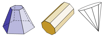
The Frustum tool was the first of the iterated solids. It can be used to create a regular right pyramid, prism, or polyhedral frustum. There are separate hide/show buttons for the front and back edges and for the colors. The given objects of the tool define the base center points, the circumradii, and the number of sides on each base. For a prism, make the radii equal. For a pyramid, make the second radius zero. The Frustum tool has these seven given objects:
(1) base 1x-y defines the horizontal location of the center of the first base.
(2) base 1z defines the elevation of the center of the first base.
(3) radius 1 defines the circumradius of the first base, as measured from point base 1x-y.
(4) base 2x-y defines the horizontal location of the center of the second base.
(5) base 2z defines the elevation of the center of the second base.
(6) radius 2 defines the circumradius of the second base, as measured from point base 2x-y.
(7) sides is a measurement defining the number of sides on each base.
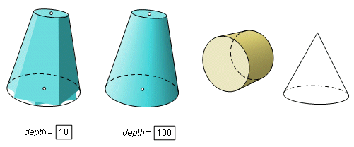
The Conic Frustum tool is now separate from Frustum. It has corresponding input objects, but uses the measurement depth in place of sides. The bases and lateral surfaces are overlapping polygon interiors. For small values of depth, the color does not fit the surface well at all. Only when the depth is increased does it begin to look right. Just as the polyhedral frustum can take the form a pyramid, the conic frustum can become a cone by giving the second base a radius of zero. For a cylinder, make the radii equal. The Conic Frustum tool has these seven given objects:
(1) base 1x-y defines the horizontal location of the center of the first base.
(2) base 1z defines the elevation of the center of the first base.
(3) radius 1 defines the circumradius of the first base, as measured from point base 1x-y.
(4) base 2x-y defines the horizontal location of the center of the second base.
(5) base 2z defines the elevation of the center of the second base.
(6) radius 2 defines the circumradius of the second base, as measured from point base 2x-y.
(7) depth is a measurement defining the number of polygons forming the colors on the lateral surface and on each base.
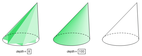
The Oblique Cone tool has the curved outline of a cone, but, as with the sphere, its color is actually made up of many polygons on both the lateral surface and the base. Since the polygons are overlapping, it has a rather irregular shape and does not look like a cone at all until the depth becomes very large. For many applications, it is simpler to hide the colors and use only the edges and outline.
Three points are required to define the cone. One is the center of the base, one is a direction point, which is any point on the normal line through the base center, and one is the vertex. It is also necessary to use a fourth point to define the base radius. To make a right cone, use the same point for the vertex and the direction point.
The Oblique Cone tool has these eight given objects:
(1) basex-y defines the horizontal location of the center of the base.
(2) basez defines the elevation of the center of the base.
(3) radius 1 defines the circumradius of the first base, as measured from point base 1x-y.
(4) directionx-y defines the horizontal location of a point on the normal through the base center.
(5) directionz defines the elevation of the point on the normal.
(6) vertexx-y defines the horizontal location of the vertex.
(7) vertexz defines the elevation of the vertex.
(8) depth is a measurement defining the number of triangles on the lateral surface, and also the number of triangles on the base.
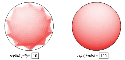
Sphere uses an iterated polygon interior construction, much like the one in Frustum. However, as you move across the surface of a sphere, the angle of incidence of the light (from a point at infinity) changes no matter what direction you move. For that reason, this construction requires a very deep iteration. The last given object is a measurement defining the square root of the iteration depth. For example, if this number is set to 100, then the actual iteration depth is 10,000. Such a large number of calculations will slow down everything else in the sketch. Consider using a parameter for this value. Use a small number at first, and increase the depth after everything is in place. It may be necessary to go into the Advanced Preferences menu and increase the maximum number of iterations. The Sphere tool has these four given objects:
(1) sphere centerx-y defines the horizontal location of the center of the sphere.
(2) sphere centerz defines the elevation of the center of the sphere.
(3) radius defines the radius of the sphere, as measured from point sphere centerx-y.
(4) sqrt(depth) is a measurement defining the square root of the depth. The number of polygonal faces will be the square of this number.
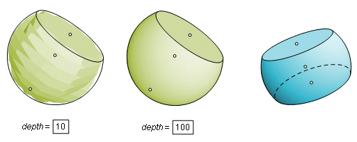
Sphere Segment is the solid that remains when a sphere is cut by a plane or by two parallel planes. It is defined by the horizontal and vertical position of the sphere center, the position of one point on the sphere (a pole), and the depth. When executing the construction, a semicircle will be centered on the x-y center point. Two points on the semicircle can be dragged to position the parallel planes. As with the Sphere tool, the depth can get out of hand in a hurry. The parameter depth defines the number of divisions of latitude and longitude, and also the number of polygons forming each of the flat faces. A point is constructed at the spherical center and at the center of each of the planar faces. When an intersecting plane is to the limit of its range, it disappears and the center point becomes a pole of the axis.
The Sphere Segment tool has these five given objects:
(1) sphere centerx-y defines the horizontal location of the center of the sphere.
(2) sphere centerz defines the elevation of the center of the sphere.
(3) polex-y defines the horizontal location of a pole of the sphere.
(4) polez defines the elevation of the pole.
(5) depth controls the depth of the iteration. See above.
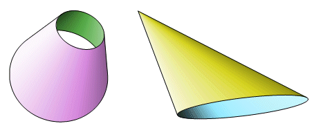
The two hollow surfaces are Hollow Conic Frustum and Hollow Oblique Cone. They have the same inputs as the corresponding solid tools. The difference is that their bases are not colored. When looking through a base, it is possible to see the interior surface. The effect is much better if the interior color contrasts with the exterior. For that reason, it was decided that there must be a separate colorbar for the interior. In order to construct one of the hollow surfaces, it is first necessary to execute Interior Colorbar, which is the same as Colorbar except for the names of certain hidden measurements.
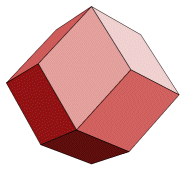
The remaining tools in this package are designed to facilitate the construction of convex polyhedra and color them parametrically. It is left to the reader to do the actual construction of the polyhedron. The job of the tools is to color and outline the faces in such a way that they can be seen only if they are turned toward the viewer, and the color of a face will depend on its position relative to the light source. Implementing these tools requires considerable patience and concentration. It is easy to get turned around, so stop after each face and turn the orientation controls to test the results.
In order to learn by example, consider the rhombic dodecahedron shown here. There are twelve faces, each of which must be colored separately. Each of the twenty-four edges must be draw twice.
In the images below, the solid is partially completed. All of the fourteen vertices have been constructed, and four of the faces (one of which is turned away) have been drawn and colored. The next face to be completed is the vertical face on the right. Three vertices of the face have been colored green and labeled.
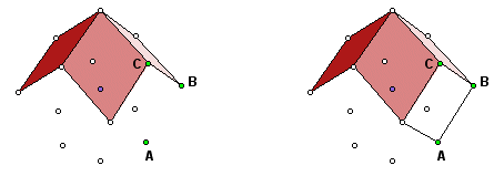
Choose the custom tool Define Plane (parametric). It requires the locations of three points in the plane of the face. Just as though you were plotting the points, define the horizontal and vertical positions of points A, B, and C in order. That requires six clicks. When it is finished, there will be no visible change in the image, but several hidden calculations lie underneath. For the Define Plane (parametric) tool, it is okay to use any three non-collinear points in the plane of the face. They must be defined in counterclockwise order.
Now choose Edge. This draws the face edges. Just click the endpoints, as with the line segment tool. Draw all of the edges, even the ones that are shared by the previously drawn faces.

Construct a polygon interior on the four vertices. Choose Face (parametric). Click the interior that was just constructed. It will be parametrically colored. The original interior still lies underneath, which is why it looks brownish in this image. Hide the original interior. Since the two interiors occupy the same region, it may be difficult to select the right one. Watch the status bar as you select. The new, parametrically colored face has a label ending with a prime (') symbol. That is the one that needs to stay.
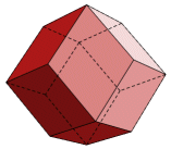 Turn the orientation controls to test the work. The new face and edges should vanish when it is turn away from the viewer. Also check to see how it responds to changes in the position of the light source.
There is one more option for the edges. The Edge front/back tool will draw a forward edge just like the one above, but it also constructs a dashed edge that appears when the face is turned away from the viewer. This gives the solid a transparent effect. On simple polyhedra it makes it possible to see the shape of the entire solid, but on the more complex solids these extra edges have a tendency to clutter the image.
Four more tools, Define Face (x,y,z), Define Face (r,theta,z), Define Face (rho,theta,phi), and Define Face (vector) serve the same purpose as Define Face (parametric). For the coordinate tools, enter the same three points in order by clicking on their coordinates. Define Face (vector) works by defining a normal vector. The first two selections define a point on the surface, then the next two selections define a point on the normal vector through the first point. The second point must be in a direction toward the interior.
Sketchpad has the ability to copy images so that they can be pasted and used in other applications, such as Word or the graphics editor that was used to create the images on this page. Usually that works out quite well, but there are some problems with some of the more complex iterated constructions. When the depth is raised to a very high value, a great number of objects are created, and the clipboard simply does not handle it all. The image suffers terribly. Most of the images on this page were created by using a screen capture instead. First adjust the scale slider so that the image is twice the desired scale. Capture the screen image. (See your graphics editor for screen capture directions.) Resize the image by a factor of 50% and save it to a graphics file (gif, jpg). The dithering that occurs with the reduction has a tendency to soften the jagged edges. The improvement is even more obvious if the images are printed.
Back to the Sketchpad Workshop
Back to Whistler Alley Mathematics