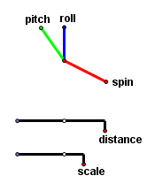
These perspective controls appear when the tool Perspective Setup is executed. The dial has the three rotation controls spin, pitch, and roll. All of the pre-image points go through the three rotations in order. In the home position (with all of the controls at 12 o’clock), the image is viewed looking toward the origin from a point on the negative y-axis. The spin control rotates all pre-image points about the z-axis. The pitch control then rotates them about the x-axis. Lastly, the roll control then rotates everything about the y-axis. The controls may be moved in any order, but the transformations will be in this order.
All of the slider controls have a zero point (violet in this image) a unit (white), and the index (red and offset). The white unit point changes the scale of the slider itself. Generally it will not be needed, but it may be useful for creating very large or very small values.
The distance slider moves the observation point in or out. If it is set too close to zero, the image will look rather distorted. It is actually correct, but for it to look natural, you would have to view it with your face pushed against the screen. Just adjust the control until it feels right. It is possible to move straight through the image by viewing it from a negative distance. This effectively reflects the image in three dimensions through a point, turning it inside out.
Moving the distance slider will not change the scale of objects on the image plane. This is equivalent to the pan-and-zoom technique sometimes used in films (see Alfred Hitchcock’s Vertigo). It has a disorienting effect. Objects appear to be drawing closer or falling away, yet their size does not change.
The scale slider simply changes the size of the image. The relative sizes and positions of objects remain unchanged.
Three buttons allow different types of projections. Perspective is the most natural looking of them. The observer is at a single point. The image plane is normal to the line between the observer and the image center. Through each point on the pre-image, a line is drawn to the observer. The image of that point is where the line intersects the plane.
When the Orthogonal Projection button is clicked, all of the projection lines are normal to the image plane. If a rectangular solid is projected this way, the edges furthest from the observer will appear too long because we are used to seeing things in perspective, where the furthest edges appear shorter. In fact, all parallel line segments have the same scale. This is like viewing the image from a point at infinity. You see a similar effect when you look through a telescope.
Clicking the Isometric Projection option creates an orthogonal projection with all segments parallel to the x-, y-, and z-axes having the same scale.
An Initialize button appears after executing Perspective Setup. Just click it once to move objects (some of which are hidden) to their initial positions. Then the button can be hidden and forgotten.

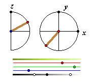
The Sundial tool constructs the sundial, which determines the direction of the light source for the parametrically colored solids found in Solid_Tools.gsp. The light source is a point at infinity. The dial in the semicircle on the left adjusts the vertical angle. The dial on the right adjusts the azimuth. This control is necessary for any of the parametrically colored solids. It is not needed for the simple solids.
The tool Colorbar also is necessary for traced solids. The top bar indicates the range of colors for the current settings. A point where the surface is tangent to the light rays will have the color of the midpoint of the top bar. From there, the color is graduated according to the angle of the light source. The next three bars are sliders controlling the red, green, and blue values for the middle of the range. The bottom bar has two sliders cotrolling the range for the sunny side and the shady side of the object. You probably do not want the shady side to be shaded all the way to black, and you may not want a white region where the surface is facing the light source, so move these sliders until you get the range you want.
Interior Colorbar is a tool that facilitates the hollow solids. It is outwardly identical to the colorbar. The hidden difference is that these colors are used only on the interior surfaces of the hollow solids.
A useful advanced tool is Freeze Sun. Normally the light source is fixed to the coordinate system, so the spin, pitch and roll controls move the sun along with all of the plotted objects, and the shading of plotted objects does not change as they turn. Executing Freeze Sun causes the light source to stay still as the system turns. This tends to give a more realistic look to moving objects. Choose the custom tool Freeze Sun and select any arbitrary point. The merged text message freeze sun will appear above the point. Now, for the purposes of lighting only, imagine that the positive y direction is straight forward and the z direction is up. Executing this tool more than once will cause major inconsistencies in the lighting. The input point is used here mainly to prevent the tool from being executed accidentally. After freezing the sun, the point and the text can be hidden.
The sundial and the colorbar are used for the parametrically colored solids only. The color of a solid is determined by the last colorbar that was created. If a new colorbar is created before each new solid, each of the solids can be assigned to a unique colorbar. The same could be done with the sundial, but that would only create an inconsistent lighting effect.
Back to Perspective Tools Manual
Back to Whistler Alley Mathematics