Here
the deflection is least on level sights, but it is never zero and does not
change sign as φ passes the horizon at 90°. Again,
inverting the scope provides a reading with compensating error. The conic locus
is moved to the opposite side, and in the deflection formula, the sign changes.
The vertical axis is not plumb.
Of the three horizontal errors, this one is, perhaps, the least significant and the
easiest to correct. It is only a matter of leveling the instrument properly.
Unfortunately though, this is one case in which the transiting capability of
the theodolite does nothing to correct the error.
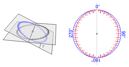
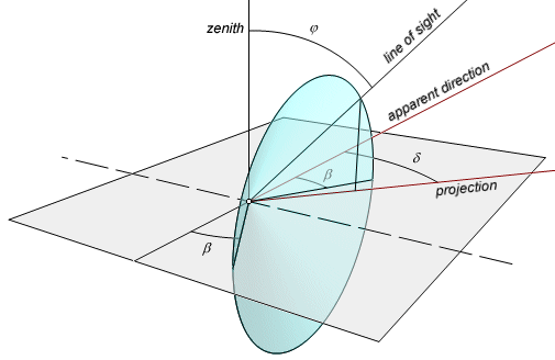
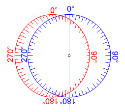
In
this image, the black scale is level and shows the true direction, but the
tilted blue scale is the one that is actually being read. There is a line of
intersection running through the middle of both scales. This line of
intersection is arbitrarily given a direction of 0° here, but it has no
relationship to the direction in which the instrument is pointed. The error can
be observed by projecting the true scale onto the plane of the instrument
scale. The (red) projection is elliptical, and the scales coincide only when
the line of sight is along or perpendicular to the line of intersection (0°, 90°, 180°, and 270°).
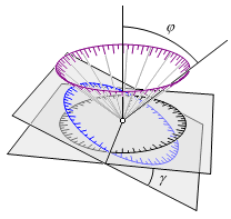
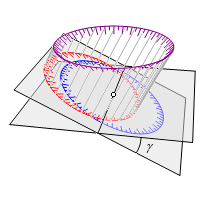
That
is not where it ends. That simplified description assumes that the line of
sight is level. Suppose that the instrument is pointed upward or downward. As
the instrument turns, assuming a constant φ, the locus of the line of sight is a cone with a vertical axis. When the true
scale is projected onto this cone, it is still true (the purple scale in the
image). This scale in turn is projected onto the plane of the instrument scale.
The result is a translation of the elliptical scale above, and it is true
only when the line of sight is perpendicular to the line of intersection (90° and 270°).
The
geometric transformation of the scale is not really so complicated, but the
corresponding analytic formula is. This is no bother since the formula has no
practical value anyway. Here δ is again the deflection of the line
of sight from the scale reading and φ is the true
zenith angle. The variable θ represents the true clockwise horizontal
angle from the line of intersection of the two planes. When the instrument is
pointed in the direction of the line of intersection, with the “vertical” axis
listing to the right, then θ is 0°.

The condition described here is an issue of leveling, and transiting the instrument does nothing to compensate for it. Check the level vials
frequently.
The vertical angle collimation is out of adjustment.
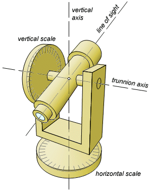
Theodolites
measure vertical angles, usually from the zenith direction, sometimes from the
horizon, rarely from the nadir. This difference affects nothing but the
arithmetic. The vertical axis should point to the zenith, but for greater
precision, theodolites have separate collimation systems so that the angle is
referenced directly to the gravity vector. This system may use a
leveling vial or a pendulum compensator, either of which can go out of
adjustment.
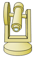
A
theodolite would make a very inefficient level (except for trig leveling,
another topic), but it essentially carries a level in its housing. The leveling
vial is equivalent to a tilting level, and the pendulum compensator does the
work of an automatic level. The theodolite actually has one advantage over most
levels. By inverting the telescope, the collimation can be checked from a
single setup.
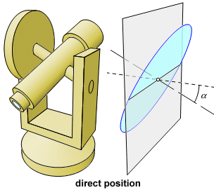
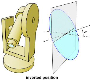
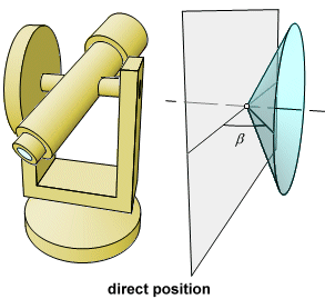
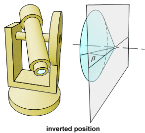
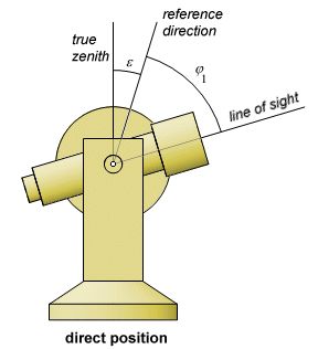
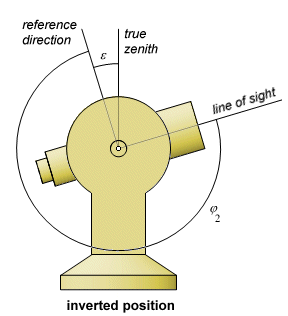
If
a vertical angle is measured in both direct and inverted positions, then the
sum of the observations should be 360°. The collimation error, ε,
will either add to both observations or subtract from both, so it will show up
in the sum of the two angles. In this picture, two observations are made on the
same stationary target. The measured vertical angle is φ1 in the
direct position, and φ2 in the
inverted position. Find ε using the formula below, and subtract it
from the direct observation to get the true vertical angle. In the
illustration, both measured angles are too small, and ε is
negative.

A
few seconds, or even minutes, of error here makes no appreciable difference in
horizontal distances, but it can play all havoc with elevations. Unlike the
horizontal angle errors, this one is constant, which is to say, it is not
affected by changes in the direction of the sight. That makes it a fairly
simple matter to correct the angle without even adjusting the instrument. In
fact, electronic instruments typically have an onboard routine that will
measure and correct the vertical angle error. Push a few buttons, sight a
target in both positions, and have the instrument store the correction. The
procedure takes only a couple of minutes, so it can be done at the beginning of each work day.
Back to The Geometry of Surveying
Last update: May 23, 2026 ... Paul Kunkel whistling@whistleralley.com
For email to reach me, the word geometry must appear in the body of the message.