The Drawing InstrumentsTo do good work, you need the proper tools.
Above is a picture of my own drafting instruments. The kit includes dividers, a compass, an extension arm, and a pen tip. Instruments like these are not being used as often these days, because most professional drafters now work with CAD systems. These instruments are high quality, but they are made to be used at a drafting table. In a high school geometry class, most drawings are done on smaller sheets of paper. Such a large compass would be difficult to work with.  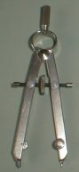
The compass at left is a typical golf-pencil compass that seems to be preferred by many of the students. I do not recommend it. The whole point of a compass is to draw an arc with constant radius. This model tends to slip easily. Friction is the only thing holding the radius. As it wears out, it becomes even looser. Also, the point is not very sharp, so it will not hold its position well when drawing. Two advantages are that it is easy to find and it is inexpensive. The compass on the right is a much better design. The wheel in the center allows for fine adjustment of the radius, and it keeps the radius from slipping. It has a much heavier construction, and will not easily bend or break. A local office supply store carries a similar model for about four dollars. That’s what it costs for a bowl of soup, if you don’t tip. 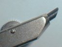
Keep the compass lead sharpened for a nice, fine curve. There are special sharpeners made just for the leads that fit the compass, but it is a simpler matter to carry a small piece of sandpaper. Stroke the lead across it a few of times to give the tip a bevel. 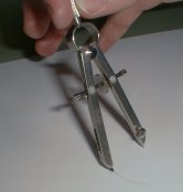
Hold the compass properly. Use one hand, and hold it by the handle at the top. Do not hold it by the limbs. If you do that, there will be a tendency to change the radius as you draw. This is especially a problem with the cheaper compasses that have no way of locking the radius. Tilt the compass back slightly, so that the lead is dragged across the page. If the compass is pushed toward the lead, it will cause the anchor point to lift up and slip out of position. Finding a good straightedge is not so difficult. Most experienced drafters would never use a ruler or a scale as a straightedge, because it mars the graduation marks. You decide how to treat your own instruments though. Many rulers have a metal strip along one edge, just for this purpose. Using a transparent plastic triangle will allow you to see your work as you draw. I like to use the edge of a pocket template. In a pinch, I have seen people use the edge of a book or a calculator, but that can be awkward. Bring the right tools for the job. Do not be impatient with your work. When using a compass, there must be some well-defined point for the center point, such as the intersection of two lines. Center the compass precisely on that intersection. Depending on the complexity of the construction, small errors may be greatly magnified. Strong Intersections, Weak IntersectionsAll points used in construction are intersection points. They can be the intersection of two lines, two arcs, or a line and an arc. Two intersections are shown in the figure below. Which intersection point is easier to pick out?
Two lines can have no more than one point of intersection, but our drawings of lines have thickness, so the drawn images intersect over a small region. In the figure on the left, that region is stretched out, so it is difficult to pinpoint the location of the point of intersection. In the figure on the right, we can get a more precise fix on the intersection. That is because the lines intersect at an angle close to 90°. The weak intersection on the left is also subject to more error. If one of the lines were misplotted by only a small amount vertically, then the point of intersection would slide to one side by perhaps five times that distance. Whenever it is possible, create strong intersections in your drawing, and you will have more precise results.
In this example an angle bisector is being constructed. Both examples use the same method, but the construction on the left uses two arcs that are nearly aligned, making their intersection difficult to pinpoint. The corresponding arcs in the construction on the right use a smaller radius, resulting in a stronger intersection, with the arcs nearing a right angle. Back to Geometry Construction Reference Last update: June 17, 2026 ... Paul Kunkel whistling@whistleralley.com For email to reach me, the word geometry must appear in the body of the message. |


